The turn-out scrap Metal Baler machine is used to compress scrap metal (steel, copper, aluminum, stainless steel, etc)into metal block or metal bale. The purpose is to save the transportation cost or reduce the raw material loss when smelting.
After compressing, the metal bale is easy to transport and store, so it can save transporation cost, reduce storage area and reduce the loss when smelting. Easy operation, durable and long service life, high efficiency, etc.
1) Hydraulic drive, compact design, great sealing;
2) Customized press box size and bale size;
3) Bale discharging ways include turn-out, side-push out and forward-out;
4) Designed with quick unit that can improve work efficiency substantially;
5) Famous motor, hydraulic system, oil cylinder, piston pump, electrical components;
6) Blades: our scrap metal baler machine with the knife, it can cut the long size material when compressing, so it very goog for the long steel wire and big size material.
Turn-out Baler, Turn-out Baling Machine, Turn-out Baling Press, Turn-out Baler Equipment, Turn-out Metal Compactor Jiangyin Metallurgy Hydraulic Machinery Factory , https://www.jiangyinyeya.com
The cross-sectional area of ​​the ground deflector should not only be calculated based on the heating conditions when the lightning current passes through, so that it will not melt due to overheating, but also have sufficient mechanical strength. The grounding body is the bottommost part of the entire lightning rod. Its role is not only to safely introduce lightning currents into the earth, but also to further spread the lightning current evenly as it flows into the earth.
The working principle of the lightning rod is, in its essence, the lightning rod is not a lightning rod, but it uses its towering air superiority to lead the lightning to itself and withstand lightning strikes. At the same time, lightning currents are leaked into the earth to protect the buildings or equipment that are nearer to it from lightning strikes. Lightning rods have a range of protection from nearby buildings or equipment that are short of lightning. This range is like a conical tent centered on a lightning rod. Objects that cover the space inside the tent can be free from lightning strikes. This is the scope of lightning rod protection.
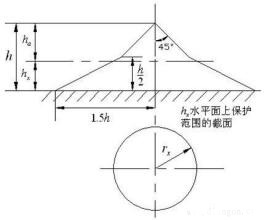
The scope of protection of a single lightning rod is shown in Fig. 1. Its specific calculation usually adopts the following method (this method is obtained from a simulation test using a laboratory impulse voltage generator). The protection radius of the lightning rod on the ground is r=1.5h. Where r is the radius of protection (m) and h is the height of the lightning rod (m). The protection radius at the height hx of the object to be protected is rx=(h-hx)p=hap;rx=(1.5h-2hx)p. Where rx—the protection radius (m) of the lightning rod on the hx level; hx—the height of the object to be protected (in meters); ha—the effective height of the lightning rod (in meters); p — the height coefficient (when the lightning rod is too high, The coefficient of protection radius is not increased proportionally). When h≤30 meters, p=1. The top angle α in Fig. 1 is called the protection angle of the lightning rod. For the plain area, α is taken as 45°; for the mountain area, the protection angle is reduced and α is taken as 37°. We use a specific example to calculate the protection range of a single lightning rod. A chimney height hx = 29m, lightning rod tip higher than the chimney 1m. Then the lightning rod height = 30m, the protection radius of the lightning rod on the ground r = 1.5h = 1.5 × 30 = 45 (m), the protection radius of lightning protection for the chimney top level rx = (h-hx) p = (30-29) × 1=1(m). 
As the scope of protection increases. The height of single lightning rods should be increased, but if the scope of protection is narrow (such as rectangular), it is not appropriate to use single lightning rods that are too high. In this case, two shorter lightning rods can be used. The scope of protection of two contour lightning rods is shown in Figure 2. The outside protection range of each lightning rod is the same as that of a single lightning rod; the middle protection range of the two lightning rods is defined by a circular arc passing through the apex of the two lightning rods and a lowest point O of the upper edge of the protection range. The height of the lowest point O from the ground is h0 in the formula—the height of the lowest point of the upper edge of the protection range between the two lightning rods (m); h—the height of the lightning rod (m); D—the distance between the two lightning rods ( m); p - high-impact coefficient. The height between the two lightning rods is the minimum width of one side of the protection range on the hx horizontal surface bx=1.5 (h0-hx). When the distance between the two lightning rods D=7hp, h0=0, which means that the two lightning rods no longer form a joint protection range at this time. When single or double lightning rods are not enough to protect all equipment or buildings, three or more branches can be installed to form a larger range of joint protection, and the scope of protection will not be described here. It should be noted that during the lightning period, near the lightning rod grounding device, due to the high stepping voltage, there is a risk of electric shock when a person approaches, and it is generally more dangerous in the range of about 10 meters in the vicinity of the lightning rod grounding device. 
Lightning rod protection scope
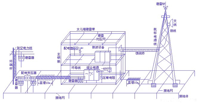
The lightning rod consists of three parts: a receiver, a ground lead wire, and a grounding body (grounding electrode). The receiver of the lightning rod refers to the metal needle at the top of the lightning rod. The position of the receiver is higher than the protected object. The ground lead is the middle part of the lightning rod and is used to connect the lightning receptor and the grounding body.