High Capacity Screw Feeder Machine High Capacity Screw Feeder Machine,Screw Feeder Components ,Screw Driver Feeder,Entrust Screw Feeder Ningbo Nbu Ad Design Co., Ltd. , https://www.nbuto.com




How to correctly design the real-time clock RTC?
RTC (Real_Time Clock) provides a time reference for the entire electronic system. The MCU, MPU, and CPU are inseparable from the RTC circuit design. What should be noted when designing an RTC unit? How to solve common RTC faults?
First, what is RTC
The real-time clock (Real_Time Clock), which is abbreviated as RTC, provides time reference for various electronic systems. The RTC integrated inside the chip is usually called an on-chip RTC, and the RTC extended outside the chip is called an external RTC.
Figure 1 Time format
Second, the development of RTC
1, early RTC
Early RTC often used 74/54 series, CC4000 series and 555 integrated circuits to build a second pulse source, and then used frequency dividers, counters, buffers, etc. to obtain timing signals of minutes, hours, days, months, and years, and finally sent them through the communication port. To the processor. Due to the complexity of circuit construction and the large impact of device characteristics, such RTCs often have poor accuracy, high power consumption, and occupy a large area of ​​PCB space, and such products are faced with the problem of “2000†(for the millennium bug problem, see Baidu).
Figure 2 Y2K problem
2. Mid-term RTC
The RTC of this period appeared in the 1990s. Due to the use of special CMOS technology, the power consumption is greatly reduced. The typical value is about 0.5μA or less, and the supply voltage is only 1.4V or less. In order to save precious IO interfaces, the communication port has also become serial, such as three-wire SIO/four-wire SPI, and some products use 2-wire I2C bus. Packaged in SOP/SSOP package, the size is greatly reduced. Thanks to the development of semiconductor technology, RTC accuracy, power consumption, and other characteristics have been substantially improved, and the perpetual calendar function has even been able to achieve automatic detection of crystal oscillation stop. At present, such RTCs are being widely used.
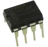
Figure 3 PCF8583
3, a new generation of RTC
The latest generation of RTC products, in addition to the full functionality of the second-generation products, incorporates composite functions such as low-voltage detection, main and backup battery switching, and anti-printed board leakage, and are inherently smaller (0.85 in height). Mm, area is only 2mm * 2mm).
Third, RTC use
The RTC design recommendation is shown in Figure 4. If an I2C/SPI-based RTC IC is used and an I2C/SPI driver is already available, the use of an RTC is particularly simple. Only the crystal oscillator circuit is required to work.
Figure 4 RTC hardware circuit
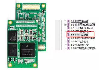
RTC design circuit is simple but not simple. The choice of clock chip, circuit design, device placement, impedance control, and PCB trace specifications all affect the stability of RTC's time reference. Figure 5 shows Zhiyuan Electronics' Cortex-A7-based architecture. The 800MHz M6Y2C-256F256LI-T core board and supporting hardware development guides, each Zhiyuan Electronics has provided the recommended circuit for each core board, providing designers with a stable and reliable design reference.
Figure 5 provides a complete hardware support core board
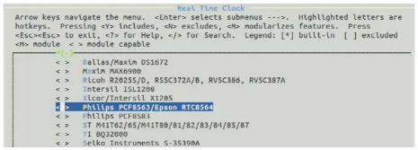
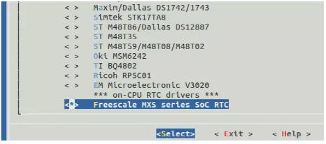
For software, we only use linux as an example to understand the use of RTC. Select the hardware-matched RTC driver in the kernel configuration to generate the correct kernel image.
Figure 6 Enable PCF8563 RTC driver
Figure 7 Enable On-Chip RTC
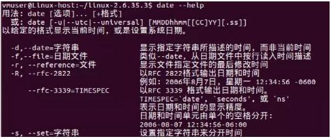
Then combine the hardware to test the RTC function and use the command date --help to get the relevant instructions. The hwclock –w command synchronizes the set time to the hardware. The hwclock command obtains the RTC time and determines whether the synchronization is successful.
Figure 8 date command (part)
Figure 9 Verifying the save status
Fourth, RTC issues
1, timing is not allowed
The main responsibility of the RTC is to provide an accurate time base. The RTC with inaccurate timing is worthless. At present, some MCUs have integrated RTC in the chip. In the actual test, the on-chip RTC deviation is 1-2 minutes under the battery-powered 6-hour environment. Therefore, if there is a higher requirement for the real-time clock, the external RTC needs to be given priority. If the temperature can be automatically compensated, the accuracy will be better. For example, the DS3231 and PCF2129 can automatically adjust the compensation amount according to the temperature change when the backup battery is powered.
Figure 10 Comparison of common RTC accuracy (for reference)
2, can not read and write
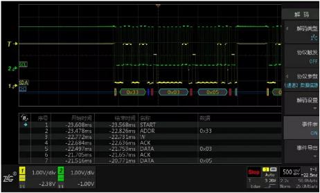
When the RTC cannot read/write (communication), it can be considered from both hardware and software. The software focuses on the communication-driven problem. In the embedded linux system, it is often shown that the RTC driver cannot detect the existence of the RTC. For example, pcf8563_get_datetime: read error is printed in the startup information, or the I2C/SPI operation cannot be performed. This type of problem can be checked and verified using an oscilloscope with protocol decoding.
Figure 11 I2C protocol decoding
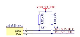
On the hardware side, taking the commonly used I2C as an example, the most important thing that cannot be ignored is the use of pull-up resistors. I2C pull-up resistor selection 1K-10K is appropriate, depending on the communication rate, length, number of nodes. When the number of nodes is large and the interference is large, resistors of about 100 to 200 ohms should be connected in series on the SDA and SCL lines to effectively suppress interference pulses. In addition, all ICs have the potential to be accidentally damaged and replace the RTC chip if necessary.
Figure 12 I2C pull-up resistors
3, do not save power off
The most likely reason for this situation is that the standby power supply is not used or the standby power supply is dead. Check the hardware power circuit. The software may set RTC in the user program and self-initiated script. The RTC will be restored to the default value each time it is restarted. At this time, the print information or system log should be checked.