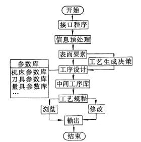
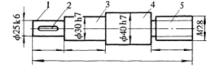
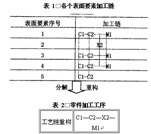
Abstract : This paper introduces the process generation method of CAPP. The process generation of parts is the reverse reasoning from the parts to the blanks, which creates the processing chain of each surface element. Through the analysis and reconstruction of the processing chain, the machining technology of the part is generated. In every aspect of CAPP, it is crucial to read information from CAD to process documentation. Among them, the creation of a process document involves many aspects: the determination of the processing method, the determination of the processing sequence, the calculation of the process dimension chain, the selection of tools and measuring tools, the selection of the machine tool, the determination of the fixture, and the design of the blank. For a successful CAPP system, it is very important to improve the above aspects. In this paper, a process chain generation and recombination method is successfully used to realize the process generation of the rotating body parts. First, the overall structure of the system The system first converts the CAD information through the interface program to the information accepted by the CAPP in order to achieve integration of the CAD/CAPP so that the required information of the CAPP does not have to be re-entered, and then the system preprocesses the information and sorts out various surface elements. The system generates its processing chain based on the processing requirements of the surface elements (processing accuracy, surface roughness, etc.), and then disassembles the processing chain and then reorganizes the processing technology of the parts. The block diagram of the system structure is shown in Figure 1. Figure 1 System block diagram Second, process generation method 1. Routing decision In Fig. 2, the shaft part has five surface elements, of which the main elements are 1, 3, 4, 5, and the auxiliary element is 2. First, the system generates the processing chain for each surface element. Establish rules for determining processing methods based on various surface features. For example, if the surface features are cylindrical and the accuracy is ≤ IT7 or the surface roughness Ra is ≤ 1.6 μm, the final machining method is grinding and the processing chain is rough. Car → Finished car → Grinding. The size and surface roughness after grinding are the dimensions and surface roughness of the part; the grinding allowance can be calculated through the machining allowance database, and the size before grinding can be calculated, ie the finish size of the finishing car; the same method can be used. Analyze and calculate the processing size and surface roughness of the roughing vehicle, and then calculate the blank size through the roughing stock. Figure 2 Parts Structure For the parts shown in Figure 2, the computer analyzes and judges each surface to determine its processing chain. The processing chain generated by each surface element of the part is shown in Table 1. In Table 1, C1 is a roughing car, C2 is a finishing car, M1 is grinding outer circle, and X2 is a milling slot (in order to be able to analyze clearly, dashed lines are drawn from top to bottom in the process chain). From Table 1, it can be seen that the processing chain of surface element 1 (outer circle) is roughing, finishing, and grinding. The system decomposes and sorts the processing chain of each surface element. The results are shown in Table 2. During processing, the same process steps are placed in the same process. For example, surface elements 1, 3, 4, and 5 are all rough-roughed, so in the roughing process, they will be combined into roughing 1, 3, 4, and 5. The various steps. For a two-way stepped revolving body part, one end is clamped for machining; then, the head is clamped and the other end is machined. Therefore, by analyzing the diameter of the outer surface of the part in advance, the system determines which element (ie, the first element) the largest diameter is, and then the left and right surfaces of the maximum diameter are naturally separated by the step sequence. For the sequence of each process, except for the sequence of the generated process chain (the same surface element), the system (for different elements) can be automatically determined by logical judgment. For example, the surface element 2 in Fig. 2 is a key groove, and the keyway process is fine. After the car, before grinding. It is determined by the principle of the process sequence, "coarse first, second, first, first, second, first and second, first". For the heat treatment arrangement, the technical requirements for the systematic analysis of the part are whether it is a preliminary heat treatment or an intermediate heat treatment or a final heat treatment, and the heat treatment arrangement principle is automatically inserted in the appropriate place of the process. As for the concentration and dispersion of processes, it is determined by the production volume, processing accuracy and complexity of the parts. 2. Determination of steps 3. The choice of machine tools In the system, the machining accuracy and specifications of various types of machine tools are stored in a computer in the form of a database. According to the processing methods, machining accuracy, and processing dimensions of the surface elements of the parts, the machine tools used are automatically determined by the decision logic. For example, the determination of a lathe is determined by factors such as the maximum outer diameter of the part, the total length of the part, and whether it is rough machining or finishing. 4. Selection of process equipment The tools, gauges, and fixtures in the system are searched by the decision logic to search for the corresponding tool, gauge, fixture library, and find matching elements to determine. Third, the system design requirements The system's hardware requirements are above the CPU486, memory 16M computer, running in the Windows environment, the system development is using the Visual c language, the database is set up with Visual Foxpro software. The modular design can effectively add, delete, and transplant certain functions, making the system easy to maintain. For the established database, the system also has the functions of modifying, printing, reporting, and querying, so that the data can be updated at any time according to production needs. The system organizes the information of the parts to make them the surface elements. The system automatically generates its processing chain for the surface elements. By analyzing, reconstructing, and combining the processing chain, the process of the parts can be successfully created.
China Electric Processor,Mini Mixer For Home-Used, 2 in 1 Electric Blender Mixer,Mini Blender Mixer, we offered that you can trust. Welcome to do business with us.
Jiangmen Hongyi Electrical Appliance Manufacturing Co., Ltd. is a professional enterprise which aims at producing household electrical appliances. Our company is located in Jiangmen City, Guangdong Province. We are adjacent to Guangzhou, Shenzhen, Macao and Hong Kong. The transportation is very convenient.
Electric Processor,Mini Mixer For Home-Used,2 in1 Electric Blender Mixer,Mini Blender Mixer Jiangmen HongYi Electrical Appliance Manufacturing CO.LTD , https://www.hongyiappliance.com
Keywords: CAD CAPP surface features 


Our company has product development, moulsd manufacturing, testing, product manufacturing and other departments. We have a professional team to ensure product quality. We provide quality and high performance products for clients. Our company aims to establish good and stable trade relationships with clients. Our products are exported to Southeast Asia, the Middle East and other countries and regions. We have deeply won consumer's trust.
Our main products are food mixers, blenders, electric fans, electric irons, plastic accessories and hardware.
Our company has consistently adhered to the concept of "outstanding quality, affordable price, excellent service". We hope to strengthen economic cooperation with friends from all over the world and create a bright future together.