Magnetic Exercise Bike,Magnetic Resistance Bike,Magnetic Stationary Bike,Magnetic Upright Exercise Bike ZHEJIANG POWERTECH CO,.LTD , https://www.chinatattoo-supplies.com
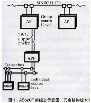
First, the boiler protection system hardware configuration The second stage unit boiler protection system (ie MFT main fuel trip system) hardware device is Siemens AS620F. The AS620F is a fail-safe device and F stands for Fail-Safe. AS620F complies with German DIN standards and U.S. VDE standards. Figure 1 shows the configuration of the AS620F. 
The FUM-F modules used in our factory are FUM310 and FUM360. The FUM310 module is a digital input module that can acquire 16 single-contact signals or 8 dual-contact signals and provides 24VDC power. The module is an intelligent module that can monitor the disconnection and short circuit of the measuring points. The front panel of the module has 16 pairs of analog jack signals. The FUM360 module is a switch output module with 24 switch output channels. Each channel provides 24VDC/l2OmA power supply. The user can be a solenoid valve, an intermediate relay or a miniature contactor.
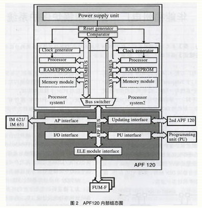
The APFl20 automatic processor is connected to the AP via a coaxial cable. In order to meet the high requirements of boiler safety, the APFl20 automatic processor is specially designed to take two internal configuration modes. That is, the APFl20 has two processors, all of which run the same program and have the same clock pulse, and the two in the APFl20. Two comparators simultaneously monitor whether the two processors are bit-coordinated. When the comparison device triggers action, if it is caused by a processor failure or memory failure, this APFl20 module will immediately stop running; due to the redundant design, the original hot spare APFl20 will immediately become the host and take over all the fault APFl20 The task, the crew will not be due to APFl20 master-slave switching and the occurrence of boiler main fuel cut. Figure 2 shows the internal configuration of APFl20. 
The boiler protection system design of our factory is very painstaking. It not only makes APF a fail-safe control system, but also guarantees the maximum availability of APF. APFl20, like its superstructure AP, also employs a redundant design (two by one structure). In this way, the interior of each APF 120 is a two-by-two structure, and the APF 120 is a two-in-one structure, and the total availability rate can reach at least three-two levels. Two APFl20 processing units have the same user program and they communicate with each other through a refresh interface in a synchronization cycle. They operate according to the principle of master-slave, that is, one APFl20 is the master; the other is the slave and can assume the function of the original host at any time without interruption.
The APFl20 of our factory is a redundant design, and its lower function modules FUM310 and FUM360 also adopt a redundant structure. APFl2O and FUM-F module communication devices, such as communication modules, communication cables, cabinet busses, etc., are also redundantly designed.
Second, the software loading and running (1) First, insert two RAM memory cards in each APFl20, and APFl20 operating switch hit "STOP" stop position.
(2) Clear the memory of both AP modules at the same time.
(3) In the engineer station ES680 (connected to the PlantBus power plant bus), clear the code of this AP and execute the following command (taking AP3 as #3 machine as an example):
Cleanas.sh-pfuzhou3-a5│teegenfile5
After clearing the code, perform the AP's hardware code generation (AP and APE software must be generated separately):
Bmag.sh-pfuzhou3-a5│teegenfile5
Bmag.sh-pfuzhou3-a5-k1│tee-agenfile5
The next step is the cross-domain of the software code (PA, APF generated separately):
Bmag.sh-pfuzhou3-a5-0│tee-agenfile5
Bmag.sh-pfuzhou3-a5-k1-0│tee-agenfile5
The last thing that needs to be generated is the LAN:
Langen.sh-pfuzhou3│teelangen_protocoll
(4) After the AP clears the code and the software is generated, the following thing to do is to send the generated code to the AP and APF to run the software.
1 Pass LAN to AP
On the ES680 software icon, select Transfer→LAN→AP. In the dialog box that opens, enter the AP number (for example, AP5). Select OK to transfer the LAN to the AP.
2 Pass the code to the AP offline to determine the location of APFl20 in the "STOP" position. On the ES680 software icon, select Transfer → AP → LOADAP (ofnnine), fill in the AP number, and then click OK. The AP and APF system software and application software are transmitted to the corresponding AP and APF. Of course, the AP system program and application program are transmitted first, and then the APF system and application program are transmitted after the AP system is completed.
3 After the code is transmitted, the AP is in the running state, usually left as the master and the slave as the right. The software of the APF machine is stored in the RAM card (an APF has two RAM cards because the APF module has two processors and each processor uses its own RAM card. The RAM card has a 3.6V button battery Therefore, as long as the battery has power, even if the RAM card is pulled out of the module, the program in the RAM card will not be lost. This design is especially suitable for the case that the APF module is damaged when the unit is in operation.) Turn the left APFl20 operation switch from "STOP" to the "RUN" position, and after a few seconds it completes the self-test operation. After the APFl20 on the left is successfully started, another APF is put into operation.
Third, the boiler protection project # 3, # 4 unit boiler protection project specifically has the following content:
(1) Manual MFT;
(2) All two blowers are out of service;
(3) Full fuel loss;
(4) All the two induced draft fans are out of service;
(5) When the turbine trips, if the high-pressure bypass valve is fully closed, and any one or more coal feeders are in operation or the number of oil guns to be put into operation is ≥11, the delay time is 10s (superheater protection action);
(6) When the turbine trips, if the low-pressure bypass valve is fully closed, and any one or more coal feeders are running or the number of oil guns to be put into operation is ≥11, the delay time is 10s (reheater protection action);
(7) When the cooling steam is running, the high-pressure bypass valve is fully closed and the time delay is 10s (reheater protection action);
(8) High water level protection of drum: Drum water level ≥ +250mm, delay 5s;
(9) Drum low water level protection: Drum water level ≥ -350mm, delay 5s;
(10) Loss of full flame;
(11) high negative pressure furnace protection: negative pressure ≥ 4kPa, delay 2s;
(12) low pressure protection: negative pressure ≤ -4kPa, delay 2s;
(13) instrument air pressure ≤ 0.55MPa, delay 2s;
(14) Total boiler air flow ≤ 25%, delay time 30s.
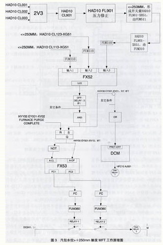
Fourth, the working principle of the boiler protection system to drum water level> +250mm trigger MFT, for example, the schematic diagram in Figure 3. The first part of the figure is the drum high water level judgment loop, which is mainly composed of five water level measuring points and a three-shot soft module FX52. The five water level measurement points include two water level switches (HAD10CL13-XG5l and HAD10CL133-XG5l) and 3 water level transmitters (HAD10CL00l, HAD10CL002, and HAD10CL003). 
The MFT signal (HHY00EY00l-XVl0=l, HHY00EY00l-XV0l=0) shuts down the corresponding equipments for powder-making, oil-supplying and ventilation fans on the furnace side. The second part in Fig. 3 is the action loop of MFT, here we take A mill as an example.
The relay changed from the original electrification to the de-energized state, and the A coal mill tripped. At the same time, another MFT signal HHY00EY00l-XVl0 is also used to trip the A coal mill. HHY00EY00l-XVl0 divides the signal into two parts via the soft module FX53 (FCl-XV53, FC2-XV54). These two signals are output to the two relays via the FUM360 fail-safe module. The two relays also become de-energized. The trip relay 2-TRIPRELAY-2 is also de-energized. The result is that the coal mill A trips. Other furnace-side equipment MFT actions are similar. It should be pointed out that the use of two trip relays in the A coal mill is mainly to ensure that such an important auxiliary machine of the coal mill can be safely and timely stopped when necessary; while in DCS DCM soft trip, FX53 hard trip and FX53 hard In the tripping, dual FUM360 failsafe modules, dual relays, and power loss actions are used to ensure that the objects protected by the protection system can move in a safe direction when the MFT occurs and when the equipment is abnormal.
V. Boiler protection system problems and solutions (l) The APFl20 module crashes during operation due to manufacturing reasons, causing the boiler to experience MFT.
Solution: Repair the APFl20 module with manufacturing problems. That is, all APFl20 modules in a series number range will be repaired. This problem has not occurred again.
(2) When exiting the steam drum water level protection, the thermal control personnel must manually remove the protection device from the furnace top.
Solution: Increase the logic of exiting the drum water level MFT protection in the software. In certain abnormal conditions (such as typhoon, heavy rain, it may cause the drum electrical contact level meter to malfunction) can easily exit the steam drum in the electronic engineering room Water level protection.
(3) MFT occurs when the first oil gun is ignited.
Solution: Do not issue the MFT when the first gun is out of ignition.
(4) The manual MFT and A-grinding once close the baffle off feedback common power.
Solution: When the standby group is overhauled, the two signals are separated so that they do not use the same power supply, and the manual MFT is mistakenly sent out due to the power failure of the template closing point.
(5) The maintenance and operation engineers of our factory believe that the MFT action circuit of the furnace side equipment is too harsh. Take the A coal mill, as long as its control loop (two fault safety module FUM360, two relays and its power supply, small switches, wiring, etc.) in any one link failure will lead to equipment jump. For the more important turbines in the same unit, the principle of tripping two to two is used, that is, the turbines will trip when two sets of parallel protections operate at the same time. We will formulate a solution by consulting Siemens and investigating methods for the brother power plant.
During the installation and commissioning of the Siemens TXP boiler protection system used in Phase 2 of #3 and #4 units of our company, many MFT malfunctions occurred due to design, manufacturing, and wiring quality. After a long period of debugging and improvement, the protective device is now working stably, and the correct rate of protection actions is 100%. No false action or refusal to move has occurred. Due to the redundant design of the equipment, maintenance during operation is easier and easier. It is a good power plant boiler protection system.
Huaneng Fuzhou Power Plant Phase II Boiler Protection System
The DCS of the 3rd and 4th No. 3 and No. 4 units of Fuzhou Power Plant adopts the Siemens Teleperm-XP (TXP for short). The boiler protection system of TXP is very different from the protection system used in Phase 1 and #2 machines. The first phase of the boiler protection system is completed by relays; while the second phase of the DCS protection system is widely used in computer technology. The boiler protection system for the second stage unit is described below. From the figure we can see that AS620F is mainly composed of AP system (automatic processing unit), AS620F system (fail-safe processor), FUM-F (fail-safe I/0 module). The auto-processing AP unit in the AS620F takes on non-safety-related tasks, and all safety-related functions are implemented in the AS620F using the FUM-F module. The importance of the comparator in the APF 120 as a monitoring unit is self-evident. All address cables, data cables, and important control cables of the two processor systems in the APFl 20 are connected to the comparator device. The comparator device is "completely self-checked" and is fully checked at specific intervals. After the values ​​of the three water level transmitters sent to the computer are averaged, they are corrected by the pressure of the steam drum and become the true value of the water level of the steam drum. This value is passed through the “+250 mm limit value determiner†to form the switch quantity HADl0FL90l-XH51. After switching the output HADl0FL90l-XH51 via the switch output module FUM5l1, it is immediately input to the fail-safe module FUM310 and reaches the FX52 three-fetch second soft module. The aforementioned two drum level switches, HAD10CL13-XG5l and HAD10CL23-XG51, also passed the FUM310 to the FX52 three-access second soft module. HADl0FL90l-XH5l, HADlOCLl13-XG5l and HADlOCLl23-XG51 three switches each take three different FUM310 modules. The purpose of this design is that even if a FUM310 module fails during operation, it will not send MFT signals by mistake, ensuring the high reliability and high availability of the protection circuit. The three soft modules FX52 in the computer will judge the above three high water level switches to decide whether to issue the MFT command. As long as any two of the three water level switches (ie, two or more) are judged as high water levels, FX52 issues an MFT command, that is, the gate output of the FX52 soft module is 0, after a delay of 5 seconds, HHY00EY00l- XV0l (NOTMFT) is also 0, HHY00EY001-XVl0 (MFT) is l. HHY00EY00l-XV0l (NOTMFT) is 0, after DCM drive module, FUM2l0 ordinary switch output module, trigger trip relay (TRIPRELAY-1) of coal mill A.