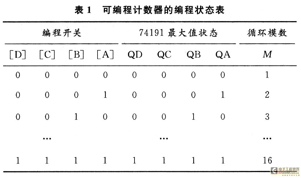
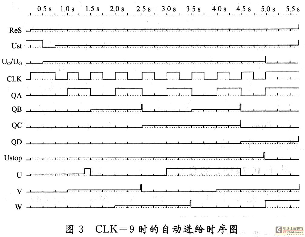
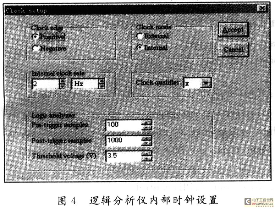
1 System Structure Block Diagram Modern machining equipment such as CNC machine tools is a manual control that uses automatic control, digital devices, or computers to completely or partially replace general-purpose machine tools. The various control functions of CNC machine tools are based on digital and text code control instructions, and are achieved through the control of digital devices. The automatic feed CNC system is the core part of modern processing equipment. It is composed of digital logic circuits. It is widely used in automatic feed control systems for numerical control equipment. Figure 1 is a logical block diagram of an automatic feed system. It consists of a position detection circuit, a control pulse generation circuit, a control gate, a pulse source, a programmable counter, a feed pulse distributor, an amplifier drive circuit, and a stepping motor. 2 Design of automatic feed control system based on IC74191 Fig. 2 is a circuit diagram of automatic feed drive system based on IC74191. Integrated Counter (74191), 4-16 Line Decoder (74159), 16 Select 1 Data Selector 74150, Programming Switch [D][C][B][A], Decoder Display Composition Status Decode Zero Programming counters. State programmable zero reset programmable counter requires 7419l preset number of terminals D, C, B, A to zero, that is, DCBA = 0000. 741191 output QD, QC, QB, QA 74159 digital input, and in The output side translates the corresponding 16 states (numbers) and then selects one of the digits through the programming switch [D][C][B][A] at 74150, outputs at the W terminal of 74150, and sends it through a non-gate circuit. To the 74191's preset number control terminal, LOAD', the 74191 can be programmed into a programmable variable counter by programming the switch [D][C][B][A]. Table 1 is the programming status table for this counter. When the tool's feed equivalent design is 6 CLK pulses, as shown in Figure 2, the programming switch value [D][C][B][A]=0110, the state of the counter is 0000,0001,0010, 0011, 0100, 0101, 0110, decoding display shows the corresponding decimal number is 0,1,2,3,4,5,6, and then stop working, waiting for the arrival of the next feed start signal. The automatic feed control circuit is composed of an input NAND gate (7410) (which constitutes an RS flip-flop), a NAND gate G (automatic feed control gate), a clock pulse signal source Us, and the like. Us is a self-excitation composed of a 555 timer. Multivibrator, the oscillation frequency is designed to be 2-5 Hz, suitable for tool feed speed of 2-5 times / s. S1, S2 open the time switch for normally open delay, and the change switch [X] replaces the position detection device and sends a negative pulse signal for position detection. The programming status table of the programmable counter is shown in Table 1. FIG. 3 is an operation timing diagram when the feed equivalent CLK=9. When the power is turned on, the normally open delay opens the timer switch S1, ontime = 0.5 ms and then turns on. The output is connected to the counter clear terminal RD, and the power is cleared. At the same time, the timing switch S2 sets the feed pulse distributor to QUQVQW=110. When the tool moves to a predetermined position, the position detection circuit will send a feed start negative pulse signal Ust. The signal is formed by the 7410 RS flip-flop in the 7410. Pin 8 outputs a high level Uo, which opens the control gate G, causes the clock pulse CLK to reach the clock input of 74163 through the G gate, and starts feeding and counting. At the same time, the clock pulse passes through the feed pulse divider and the power amplifier circuit. Drive the stepper motor of the automatic feed actuator; When the tool reaches the preset feed position, use the down signal Ustop appearing on the LOAD' end of the 74163, act on the RS flip-flop, and output low power on pin 8 of the 7410. When the control gate G is closed, the clock pulse is disabled and the stepping motor stops rotating to complete an automatic feed duty cycle. 3 Simulation of automatic feed control system Perform computer simulation experiment on the automatic feed drive system of CNC machine tool shown in Fig. 2. Double click the icon of virtual digital logic analyzer to open the Clock setup dialog box and adjust the internal clock setting, as shown in Fig. 4 , Make Internal clock rate = 2 Hz, set the feed amount through the programming switch, press the switch [X] key after the power is turned on, send out the position detection negative pulse signal, the automatic feed drive system starts to work, virtual digital logic analysis The instrument obtains the waveform of each point shown in FIG. The number of feed pulses can be displayed by a seven-segment decode display LED, see Figure 2. When the programming switch value [D][C][B][A]=1111, 15 feed pulses are output. The simulation and experimental results fully meet the design requirements. 4 Conclusion <br> Stepper motor automatic feed drive system is the core component of CNC machine tools, feed control using programmable variable counters, programmable logic switches instead of mechanical band switch, easy online operation, improve work stability Reliability, reliability and service life; EDA software is used to study and design the automatic feed system of CNC machine tools, which can easily change the circuit and parameters according to process requirements, observe the simulation results, shorten the design cycle, and provide the circuit design and implementation. Basic basis.
Flat Bags on Roll is commonly used in every industry, such as electronically products, accessories,household, cosmetic, commodity, stationery, toy, fruits,vegetable and food products etc. Specially in packing of fresh fruits, fresh vegetables, meat, seafood, cakes,chocolates, candy, cookies,biscuits and so on.
The bags could be in big roll for industry and supermarket or in small or for household.
Flat Poly Bags,Flat Plastic Bags,Flat Polypropylene Bags,Flat Poly Bags On Rolls,Roll Bags,Plastic Roll Bags,Freezer Bag Rolls BILLION PLASTIC MANUFACTURING CO.,LTD, JIANGMEN , https://www.plastics-billionjm.com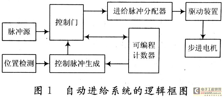
The 3D flip-flop in the 4D flip-flop (74175) in FIG. 2 constitutes a feed pulse distributor, ie, a circular distributor. The feed pulse distributor distributes the feed pulses to the windings of each phase of the stepping motor in turn in a certain order. Circuits, their circuit forms and stepper motor structure, model and control methods. The stepping motor of this system adopts the three-phase six-shot excitation method. The conduction order of the three-phase winding is U→UV→V→VW→W→WU→U. Before the feed pulse CLK arrives, the feed pulse distributor resets first, and then it is set to QUQVQW=100 through the time switch S2, ie DU=1, DV=1, DW=0, after the first CLK pulse, the ring distribution The output of the device is QUQV, QW=110, which can list the status of each output and drive terminal of the feed pulse distributor as shown in Table 2. The driving equations of each trigger drive end are: 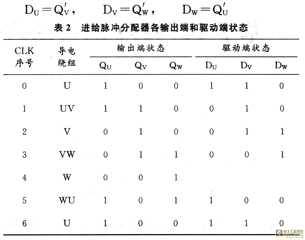


Design and Implementation of Automatic Feed Control System Based on IC74191
The automatic feed control system is an important part of modern processing equipment such as CNC machine tools. Requires the digital scale integration counter in IC74191 as the core and the stepper motor as the actuator to design a digital automatic feed control system. The EDA software is used for the research and design of the automatic feed control system, the system simulation circuit is created, and the simulation results are given. The tool feed speed is required to be 2~5 times/s; the waveforms of each point are observed using a virtual digital logic analyzer and oscilloscope; the number of feed pulses can be displayed by the LED seven-segment decoding display.